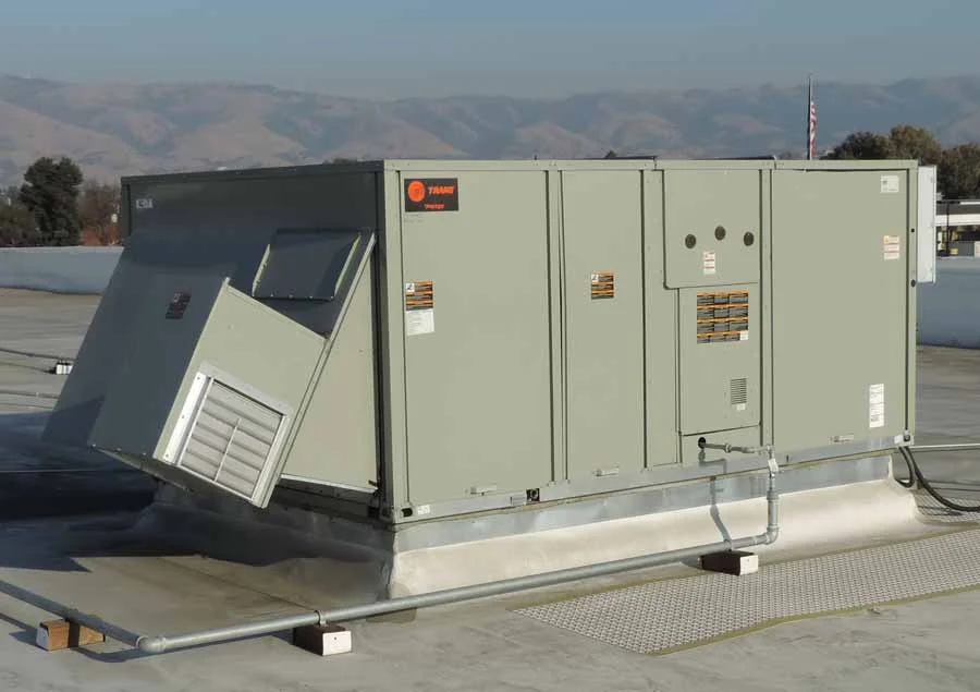
Commercial air handlers flood ceilings due to improperly sized condensate P-traps that cannot overcome the unit's negative static pressure, leading to condensate blowout. Proper sizing, as performed by Western Mechanical, Inc., requires the trap depth to exceed the total negative static pressure by at least 1 inch water column, plus a vent tee, ensuring continuous drainage. This precise calculation prevents overflow and water damage. Our UA Local 250 journeymen ensure compliance with ASHRAE standards. Contact us at (661) 251-0111 for expert service. CSLB #618138.
Engineering Tolerances & Governing Standards
Parameter
Specification
Standard
Minimum P-Trap Depth (Draw-Through)
Total Negative Static Pressure (in. w.c.) + 1.0 in. w.c. Safety Seal
ASHRAE 170 / SMACNA HVAC Duct Construction Standards
Condensate Drain Line Slope
Minimum 1/8 inch per foot (1:96)
IMC 307.2.2 / UPC 804.2
Maximum Horizontal Run Before Vent
15 feet (for 3/4 inch drain)
Local hydronic piping Codes / Manufacturer Guidelines
P-Trap Material
Schedule 40 PVC or Copper
ASTM D1785 (PVC) / ASTM B88 (Copper)
Vent Tee Placement
After P-trap, before vertical drop or main drain connection
ASHRAE 170 / Manufacturer Specifications
Understanding Negative Static Pressure in Draw-Through RTUs
Draw-through rooftop units (RTUs) are ubiquitous in Southern California commercial and industrial facilities, designed with the evaporator coil placed upstream of the supply fan. This configuration creates a significant negative static pressure zone within the coil section, effectively pulling air through the coil. When the condensate drain pan is located within this negative pressure region, the pressure differential can literally suck the water out of an undersized P-trap, breaking the water seal and allowing the negative pressure to pull air into the drain line instead of allowing condensate to flow out. This phenomenon, known as 'P-trap blowout,' leads to immediate condensate overflow from the pan.
The critical consequence of P-trap blowout is the rapid accumulation of condensate within the drain pan, which then overflows onto the ceiling below or into the equipment itself. This is often observed as water stains or active leaks that mysteriously stop when the unit cycles off, as the negative static pressure dissipates. Western Mechanical, Inc. meticulously calculates the total negative static pressure, which is a function of fan speed, coil pressure drop, and ductwork resistance, to ensure the P-trap depth is engineered to consistently overcome this force, typically requiring a minimum 1-inch water column safety margin beyond the measured negative pressure.
Engineering the Proper P-Trap Depth and Configuration
Correctly sizing a condensate P-trap for a draw-through RTU involves a precise calculation: the trap's vertical depth must be greater than the maximum negative static pressure (in inches of water column) present in the coil section, plus an additional 1-inch water column safety seal. For instance, if the measured negative static pressure is -1.5 inches w.c., the P-trap must have an effective depth of at least 2.5 inches w.c. to maintain its seal. Failure to adhere to this fundamental principle guarantees condensate issues, leading to costly repairs and potential operational downtime, particularly in sensitive environments like data centers or healthcare facilities (HCAI PIN 70).
Beyond depth, the P-trap's configuration is equally vital. A properly installed vent tee, positioned after the P-trap but before any significant vertical drop or connection to a main drain line, is essential. This vent prevents siphoning effects that could prematurely break the trap seal and ensures atmospheric pressure is maintained at the trap outlet, facilitating continuous gravity drainage. Our UA Local 250 signatory journeymen at Western Mechanical, Inc. are expertly trained in these precise installations, adhering to ASHRAE 170 and local hydronic piping codes to guarantee robust, leak-free condensate management systems for all commercial and industrial applications.
Lifecycle ROI and Preventative Maintenance for Condensate Systems
Investing in correctly engineered condensate P-traps and drainage systems provides significant lifecycle return on investment (ROI) by preventing catastrophic water damage, mold growth, and premature equipment failure. For Southern California facilities, where humidity can fluctuate, consistent condensate removal is paramount for indoor air quality and structural integrity. The cost of repairing water-damaged ceilings, electrical components, or contaminated insulation far outweighs the initial investment in proper P-trap design and installation. Proactive maintenance, including regular cleaning and inspection of drain pans and traps, is also critical to prevent blockages from algae or debris.
Western Mechanical, Inc. emphasizes a holistic approach to condensate management, integrating P-trap sizing with overall RTU performance and preventative maintenance schedules. Our comprehensive service includes verifying drain pan integrity, ensuring proper slope for gravity drainage (minimum 1/8 inch per foot), and confirming that all drain lines are free of obstructions. This meticulous attention to detail, performed by our CSLB #618138 licensed technicians, ensures optimal system efficiency, extended equipment lifespan, and compliance with health and safety standards, safeguarding your facility's assets and operational continuity.
UA Local 250 Certified Field Diagnostic & Commissioning Protocol
Verify RTU manufacturer's specified negative static pressure at coil section using a digital manometer (e.g., Testo 510i).
Measure existing P-trap depth and compare to calculated minimum required depth (Negative Static + 1" safety seal).
Inspect drain pan for proper slope towards drain connection, ensuring no standing water or microbial growth.
Confirm presence and correct placement of vent tee after the P-trap to prevent siphoning and ensure atmospheric break.
Perform a condensate flow test by introducing water into the pan, verifying continuous drainage without overflow or trap seal loss under full blower operation.
Facility Director & Chief Engineer FAQs
Why does my RTU leak only when the blower runs?
This is a classic symptom of an undersized condensate P-trap. When the blower operates, it creates negative static pressure that can pull air through an inadequate trap, breaking the water seal and causing condensate to overflow the pan. Western Mechanical, Inc. can diagnose and correct this issue.
What is the '1-inch safety seal' for P-traps?
The 1-inch safety seal is an additional depth added to the calculated minimum P-trap depth. It provides a buffer against minor pressure fluctuations, ensuring the water seal remains intact even if the unit's negative static pressure varies slightly during operation, preventing blowout.
Can a clogged condensate drain cause P-trap issues?
Absolutely. A clogged drain line or P-trap can prevent condensate from flowing, causing the pan to overflow regardless of the trap's design. Regular cleaning and inspection are crucial to maintain proper drainage and prevent blockages from algae, dirt, or debris.
Does the drain line slope matter for P-trap function?
Yes, proper drain line slope (minimum 1/8 inch per foot) is critical for gravity-driven condensate removal. Insufficient slope can lead to standing water, slow drainage, and contribute to overflow issues, even with a correctly sized P-trap. Our CSLB #618138 team ensures compliance.
Acton Headquarters & 24/7 Southern California Dispatch
Western Mechanical, Inc. • 2210 Soledad Canyon Road, Suite O, Acton, CA 93510 • Primary Phone: (661) 251-0111 • 24/7 Toll-Free: (800) 585-5085 • CSLB #618138 (C-20, C-38, C-4)